Figure 1. - wideband rf amplifier with shunt feedback and emitter degeneration
LAST MODIFIED:
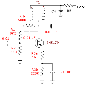
Wideband rf transformers are simply transfomers designed to provide an impedance transformation over a broad frequency range. In amateur radio applications we wind these transformers on ferrite toroids. A common impedance transformation is 200 ohms to 50 ohms using a bi-filar winding. Here is an example from our broad band amplifiers tutorial.
Figure 1. - wideband rf amplifier with shunt feedback and emitter degeneration
Transformer T1 is a broadband rf transformer.
In the design of these kinds of wide band rf transformers the primary reactance is usually around 5 times the primary impedance. With a 200 ohms to 50 ohm transformer, we would allow a reactance of 1,000 ohms at the lowest frequency of interest. Just as an example consider we were building a broad band amplifier for the amateur bands and going down as low as 1.8 Mhz.
For this example we would need bi-filar windings which have a reactance of 1,000 ohms at 1.8 Mhz, this means a required inductance of around 88 uH. A look through the Amidon data book tells me that ferrite toroid FT-50-61 as one example can provide me with an AL factor of 68mH / 1000 turns.
This means if 1,000 turns were wound on the toroid it would give us 68 mH. Yes that IS milli-henries, these are ferrite toroids.
To wind a wide band rf transformer with an inductance of 88 uH (yes that's micro-henries) which is in fact 0.088 mh we use the following formula:
Turns = 1,000 X SQRT (L in mH / AL factor) = 1,000 X SQRT (0.088 / 68) = 36 turns.
Our wide band rf transformer needs 36 turns to achieve an inductance of 88 uH.
Because this is a bi-filar winding for our wide band rf transformer, we need two lengths of wire which we will "twist" together at a "pitch" of 2.5 turns per inch or 1 turn per 10 mm. If you anchor one end of the two wires together in a bench vise and fix the other ends securely in a hand drill (a bent nail or fish hook helps here) you then gently "stretch" the wires first. Then you slowly turn the hand drill and notice the two wires "twisting" together, as you proceed you will notice more and more twists appearing. Stop when you have about 2.5 twists to the inch. Stretch the wires once more.
Wind 36 turns through the toroid and that is it! To use in an application such as figure 1 above you need to pay attention to the "phasing". Notice the two dots on T1 above? They indicate the start of each wire. Use an ohmmeter to find the start and finish of one winding, mark it in some convenient manner e.g. coloured pen. The other winding should then be obvious.
Coilcraft is one manufacturer of wide band transformers which provide reliable performance.
The transformers are offered in tapped or untapped configurations and are packaged in a low-profile DIP-style plastic case. All parts are available in either a surface mount version or a through-hole version that�s compatible with standard DIP sockets.
Applications include impedance matching, voltage or current transformation, DC isolation, balanced / unbalanced mixing, matching, power splitting, coupling, and signal inversion. Custom wide band transformers with special combinations of impedance ratio, insertion loss, frequency response, and current handling are also available.
Alright what if you need something other than a 200 ohm to 50 ohms transformer, how would you go about it?
What I tell you here now is applicable from DC to daylight. What that means is, it is equally applicable to an audio transformer with a bandwidth of 100 Hz to 3,000 Hz (for an audio transformer) as it is to a broadband transformer designed to operate at say 7.00 to 7.50 Mhz. Read on.
Firstly you need to pick either a lower 1 dB or 3 dB bandwidth. Wozzat??? Look at figure 2 below where I present my usual scungy drawing - I'm no good at this graphic arts caper, not the program, just my lack of artistic talent.

Figure 2. - band pass filter characteristics
Here I've crudely depicted a range of frequencies being passed by a filter and indicated the 1 dB and 3 db points. A 1 db point is where the power output is about 80% of the band pass power or 90% of the voltage level. A 3 db point is where the power output is about 50% of the band pass power or 70.7% of the voltage level. If you can't understand decibels then you need to look at the decibel page
In your broad band transformer you need to determine the lowest point you can tolerate in frequency. Entirely for discussion purposes I've selected 5 Mhz for both 1 dB and 3 dB to demonstrate the formulas. Also I'm going to construct a broad band tranformer to operate between 14.4 ohms and 50 ohms.
For the 1 db point to be 5 Mhz, I use the formula Lp = R / ( 2 X Pi X Fo) and for the 3 dB point, I use the formula Lp = R / ( 4 X Pi X Fo). The general formula for any other dB level is a bit difficult to reproduce here but contact me and I'll give it to anyone who wants it.
The first formula simply gives you an inductance equal the reactance of R or in our case we're using 14.4 ohms at 5 Mhz. This results in an inductance of 0.458 uH. The second formula simply produces half that inductance or, 0.229 uH.
Back to the result of 0.458 uH, that could easily be achieved with 10 turns on a T-50-2 toroid. Alright we have a T50-2 toroid with 10 turns on it, this is supposed to represent 14.4 ohms at 5 Mhz. To match to 50 ohms all we have to do is work out the turns ratio. Impedance transforms as "the square of the ratio of turns". Then 50 / 14.4 = 3.472' and the square root of this is 1.86 so we need on the secondary 1.86 times more turns or in our case 19 turns.
IF our output were terminated in a genuine 50 ohm load then the square of [19 /10] being the turns ratio would be reflected back giving (if you work it out) a source of 13.85 ohms.
The CRITICAL aspects here are: a) turns ratio AND; b) final termination being a genuine 50 ohm load.
The high frequency limit is influenced by the leakage inductance Lk and distributed capacitance of the inductor forming a second order low pass filter and is influenced by a very wide range of factors. The higher the inductance, then the lower or flatter the low-frequency end but, this comes at a price of higher Lk and distributed capacitance limiting high frequency response. Often a compromise is needed for high ratios of frequencies. Although I have never tested it, I would imagine at least one octave bandwidth could easily be accomodated e.g. 2.5 Mhz to 5 Mhz or 5 Mhz to 10 Mhz.
broad band amplifiers
tuned circuit amplifiers
impedance
inductance
reactance
NEW! - How to link directly to this page
Want to create a page link to me from your site? It couldn't be easier. No HTML knowledge required; even the technophobes can do it. All you need to do is copy and paste, the following code. All links are greatly appreciated; I sincerely thank you for your support.
Copy and paste the following code for a text link:
and it should appear like this:
<a
href="https://www.electronics-tutorials.com/basics/wide-band-rf-transformers.htm"  target="_top">visit VK2TIP's Wide Band RF Transformers</a>
visit VK2TIP's Wide Band RF Transformers Page
the author Ian C. Purdie, VK2TIP of www.electronics-tutorials.com asserts the moral right to
be identified as the author of this web site and all contents herein. Copyright © 2000 = 2001, all rights reserved. See copying and links.
These electronic tutorials are provided for individual private use and the author assumes no liability whatsoever for the application, use, misuse, of any of these projects or electronics tutorials that may result in the direct or indirect damage or loss that comes from these projects or tutorials. All materials are provided for free private and public use.
Commercial use prohibited without prior written permission from www.electronics-tutorials.com.
Copyright © 2000 - 2001, all rights reserved. URL - https://www.electronics-tutorials.com/basics/wide-band-rf-transformers.htm
Updated 27th February, 2001