
Figure 1 - outline schematic of a hartley oscillator
Hartley oscillator are inductively coupled, variable frequency oscillators where the oscillator may be series or shunt fed. Hartley oscillators have the advantage of having one centre tapped inductor and one tuning capacitor. This arrangement simplifies the construction of a Hartley oscillator circuit.
First off let's look at a schematic of a hartley oscillator.
Figure 1 - outline schematic of a hartley oscillator
Here I'll present the schematic for my old favourite, together with a buffer stage and an amplifier stage which should deliver about 5V P/P into a 50 ohm load. We'll discuss each relevant stage and produce some rule-of-thumb design info. Because the consensus comes down in favour of FETS and I'm big enough to lay aside my prejudices in the noble cause of advanced education we'll use a FET oscillator. Nothing to do with a few friends who might
belt me up!
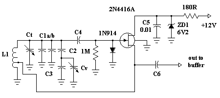
Figure 2 - schematic of a hartley oscillator
For this design I'm going to say we will be constructing a general purpose VFO to operate at 5000 - 5100 Khz no particular reason, pick anything you like.
Now I chose a 2N4416A FET purely because I bought a big bag of them years ago and have them on hand. You could use any general purpose JFET you can readily obtain. Note the 2N4416A is a metal can and the case is grounded.
The frequency determining components are L1, Ct (a nominal 10 pf trimmer), C1a, C1b, C2, C3, Cv and C4.
Note: I have been asked a number of times the function of C4 in this circuit. Capacitor C4 is to reduce the loading on the tuned circuit components. It may be as small as possible consistent with being able to provide sufficient drive to the succeeding buffer amplifier stage. Often the home constructor will often make C4 a trimmer.
The other components are bog standard. The two resistors, silicon diode and zener diode need never change, capacitor C5 is about right for this frequency. C6 can be selected to give higher / lower output to the buffer amplifier. Smaller C6 values give lower output and conversely higher values give larger output. The silicon diode I'll explain later, the zener diode is to give a regulated 6.2 volt supply.
Now there is NOTHING sacred about my frequency determining capacitor combination O.K.? Too many people look at these kind of circuits and think they must duplicate everything literally, not so. This is just a typical representation. C1 to C3 plus Cv and Ct are just a combination of parallel and some series capacitors all designed to give us a bit of flexibility with the tuning range. Cv could easily be replaced by two back to back tuning diodes.
What you need to do to get the circuit to work is to have an inductive reactance for L1 of around about 180 ohms. At 5 Mhz this works out at about 5.7 uH and, if you don't know how I arrived at that figure I seriously recommend you spend some time on my other tutorials such as Basics and LC Filters.
The important aspect is that the feedback point from the source of the JFET connects to about 25% of the windings of L1 from the ground end. Now I've depicted an air cored inductor. It could be, just as one example among a great many, 18 - 19 turns of #20 gauge wire on a 25.4 mm (1") diameter form spread evenly over a length of about 25.4 mm (1"). The tap would be at about 4 1/2 turns. Check that out with the formula's I taught you elsewhere.
Alternatively, with degraded performance, you could use a T50-6 toroid and wind say 37 turns of #24 wire (5.48 uH) tapping at 9 turns. The AL factor for a T50-6 is 40. Again do the other tutorials if necessary, I'm not going to repeat old work and it's going to be even harder from here on. I'll thoroughly explain new concepts, not the old.
So if we are to have our oscillator working at about 5 Mhz, we know the LC is 1013 and if L is say 5.7 uH then total C for resonance (just like LC Filters eh!) is about 177 pF. We want to be able to tune from 5000 to 5100 Khz a tuning ratio of 1.02 which means a capacitance ratio of 1.04 (min to max).
Let's fiddle with some numbers! I have a Jackson Bros. air variable capacitor (very Rolls-Royce) which swings from 10.5 pF to 105 pF, a typical 10:1 ratio in air variables. This I will use for Cv.
If the total swing is 1.04 (actually 1.0404:1) and Cmax is 177 pF it follows Cmin is 170 pF. A variation of only 7 pF (roughly). Now we're treading on unsafe ground here with such a large variable capacitor. We could:
A) rip plates off it to reduce capacitance (don't even think about it)
B) go to varactor diodes with a small swing. That's O.K. but performance becomes degraded.
C) obtain a smaller air variable with Cmax of say 25 pF.
Just to prove I'm a glutton for punishment and if you're still here so are you, we will purely for the mathematical exercise, persevere with the 105 pF variable. What if we eliminate C3 and make C2 = 15 pF NPO then the series combination of C2 and Cv swing 6.176 pF to 13.125 pF, a variation of over 6.9 pF - are you lost? Go back to the other tutorials on capacitance.
If our Cmax was 177 pF then 177 - 13.125 = 163.875 and the 177 pF was approximate anyway. I'd make Ct a 10 pF air trimmer (if available, if not, a ceramic or whatever the supplier offers but 10 pF max.). That leaves about 154 pF to make up. How about making C1a and C1b into 3 NPO capacitors of say 2 X 47 pF and 1 X 56 pF all NPO types. In total that comes to less than 177 pF max. but don't forget there are stray capacitance's in the circuit. In the final wash-up you could simply use 3 X 47 pF.
Here's what we finish up with

Figure 3 - final schematic of a hartley oscillator
The frequency is simply varied by the net value of C in the tank circuit.
The output amplitude remains constant when tuned over the frequency range.
The feedback ratio of L1 to L2 (figure 1) remains constant.
The output is rich in harmonic content and therefore not suitable where a pure sine wave is required.
broad band amplifiers
buffer amplifiers
colpitts oscillators
crystal oscillator
emitter degeneration
negative feedback
oscillator basics
voltage controlled oscillators
oscillator drift
NEW! - How to link directly to this page
Want to create a page link to me from your site? It couldn't be easier. No HTML knowledge required; even the technophobes can do it. All you need to do is copy and paste, the following code. All links are greatly appreciated; I sincerely thank you for your support.
Copy and paste the following code for a text link:
and it should appear like this:
<a
href="https://www.electronics-tutorials.com/oscillators/hartley-oscillator.htm"  target="_top">visit VK2TIP's Hartley Oscillators Page</a>
visit VK2TIP's Hartley Oscillators Page
the author Ian C. Purdie, VK2TIP of www.electronics-tutorials.com asserts the moral right to
be identified as the author of this web site and all contents herein. Copyright © 2000 - 2001, all rights reserved. See copying and links.
These electronic tutorials are provided for individual private use and the author assumes no liability whatsoever for the application, use, misuse, of any of these projects or electronics tutorials that may result in the direct or indirect damage or loss that comes from these projects or tutorials. All materials are provided for free private and public use.
Commercial use prohibited without prior written permission from www.electronics-tutorials.com.
Copyright © 2000 - 2001, all rights reserved. URL - https://www.electronics-tutorials.com/oscillators/hartley-oscillator.htm
Updated 25th January, 2001